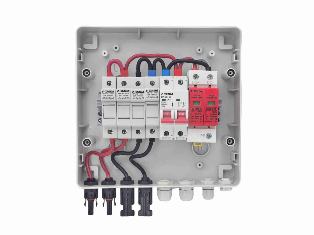
Modern low voltage power distribution networks rely on protective devices to prevent electrical fires and conductor damage during current overloads. Among these components, the miniature circuit breaker stands as a fundamental defense element inside industrial control cabinets and commercial distribution panels. Understanding the mechanical, thermal, and electromagnetic forces inside these compact devices allows plant engineers to maintain power reliability.
This article explores the internal physical mechanisms governing miniature circuit breaker operation, focusing on bimetallic thermal deflection, electromagnetic solenoid trip dynamics, and plasma arc extinction inside the arc chute
Thermal protection defends power distribution conductors against sustained overcurrent conditions where current magnitude moderately exceeds nominal capacity over an extended time.

Direct short circuits represent low impedance faults where current magnitudes rapidly surge to thousands of amperes, requiring millisecond isolation.
Separating energized contacts under high fault currents ionizes surrounding gas molecules, creating a conductive plasma arc channel exceeding several thousand degrees Celsius.
Having analyzed the internal thermal, magnetic, and arc suppression physics operating inside protective equipment, let us examine how manufacturers translate these physical mechanics into calibrated operational curves for real applications.
To prevent nuisance tripping while guaranteeing short circuit protection, breakers are calibrated to specific trip curve profiles defined by their magnetic threshold ranges.
| Curve Type | Magnetic Tripping Threshold | Typical Applications |
| Type B | 3 to 5 times rated current | Pure resistive loads, residential lighting, and long conductor paths |
| Type C | 5 to 10 times rated current | Commercial lighting, ventilation fans, and control transformers |
| Type D | 10 to 20 times rated current | Industrial motors, arc welders, and heavy transformers with intense inrush surges |
Specifying circuit protection requires analyzing key standardized metrics beyond nominal current capacity.
When choosing components designed around these demanding electrical thresholds, equipment builders routinely turn to established suppliers like SHANGHAI DADA ELECTRIC CO.,LTD to ensure verified compliance with international quality standards.
Understanding these technical parameters allows engineers to evaluate how environmental variables alter real world protective performance inside electrical cabinets.
Because thermal overload protection relies on physical heat accumulation inside the bimetallic element, external ambient temperatures directly alter tripping thresholds.
When protective devices interrupt a downstream circuit, technicians follow structured diagnostic routines to isolate the underlying cause.
To source robust protective devices manufactured for demanding commercial and industrial applications, review the comprehensive range of Miniature Circuit Breaker units built for modern power distribution systems.
A frequent error is sizing wire solely based on nominal load current without factoring in breaker thermal derating or terminal temperature limits. Connecting undersized conductors creates high resistance hot spots at terminals, causing premature thermal tripping.
Excessive humidity promotes internal spring corrosion and metal contact oxidation, increasing electrical resistance over time. In harsh industrial environments, non tropicalized units suffer from contact welding or degraded mechanical response times.
Standard production models ship quickly from stocked inventories, whereas custom voltage configurations, special trip curve calibrations, or private label branding orders typically require four to eight weeks for manufacturing and quality testing.
Understanding the thermal deflection physics, electromagnetic solenoid dynamics, and arc suppression mechanics operating inside low voltage protective equipment allows engineers to design safe, resilient electrical networks. Matching thermal magnetic characteristics to specific electrical loads eliminates costly operational downtime while protecting infrastructure against catastrophic fault conditions.
Partnering with experienced equipment manufacturers ensures your distribution infrastructure meets strict global safety standards. Explore customized power engineering Solutions to enhance your facility protection systems with certified electrical devices.

 0086-15167477792
 charlotte.weng@cdada.com

No.171 Yezhuang Road, Zhuanghang, Fengxian, Shanghai, China